Building an IBM 3270 terminal controller
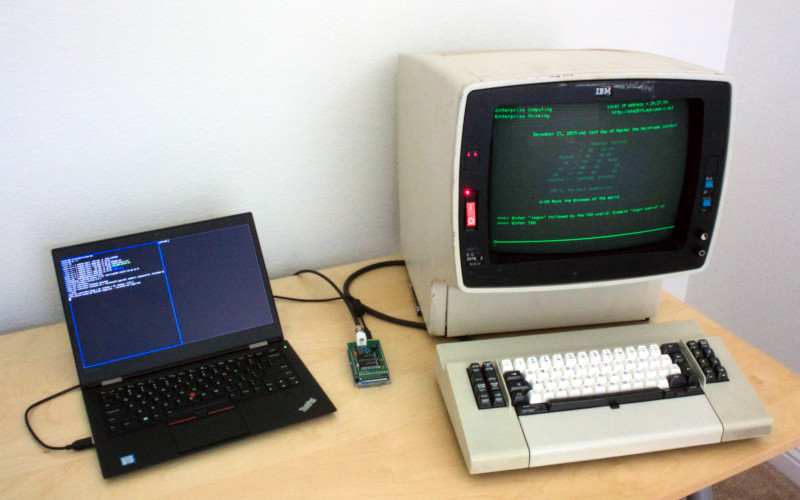
The IBM 3270 type terminal is a mainframe computer terminal. I've long been fascinated by the IBM mainframe, and especially these terminals. Early models such as the 3278 and 3279 have a unique aesthetic, and their block-oriented design is so different from the ubiquitous VT series terminals.

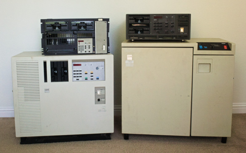
I'm not alone in wanting to connect a real IBM terminal to the Hercules emulator. Unfortunately, it's difficult to find the necessary IBM 3174 terminal controller with Ethernet or Token Ring interface, version of the software that supports TCP/IP and in working condition. Also, they are large, noisy, and difficult to maintain, given the software is loaded from an uncommon 2.4 MB 5¼-inch floppy disk - if you are lucky, there is a 20 MB hard disk option. So I decided to build my own and learn a little in the process.
Some IBM 3270 history
According to IBM, the 3270 information display system was introduced in 1972, the iconic 3278 terminal 5 years later, in 1977. Color terminals arrived in 1979 with the 3279. Mixing IBM model numbers and dates is very confusing!
The 3270 is one of the most recognizable block-oriented terminals. The 3270 data stream allows the programmer to describe a screen containing protected text, unprotected fields, and formatting attributes. Unprotected fields allow you to input or modify data. Instead of sending every key you press to the host immediately, as is the case with a character-oriented terminal, the terminal stores the input until you press an attention key - such as enter. Only when you press an attention key is the input sent to the host, this improves the perceived response time over a slow or unreliable connection. It also reduces the host processing requirements allowing many more terminals to be connected to a host than could be with character-oriented terminals. It's not that different from an HTML form.
Exciting peripherals were available on early 3270 terminals, including light pens for improved navigation and magnetic card readers; unfortunately, I've never seen these on eBay.
Terminals are connected to a controller by coax cable in a star topology. A balun can convert this to more common twisted pair cabling, although I think IBM would prefer you use their cabling system. The controller is connected to the mainframe by different interfaces depending on whether it is a local or remote controller and year, interfaces include:
- Parallel Channel
- ESCON Channel
- X.21
- V.35
- Token Ring
- Ethernet
As a result, IBM 3174 and 3274 controllers come in many different shapes and sizes - from small desktop units, medium rack-mount, and large floor standing units.

Other companies, including Memorex, manufactured compatible terminals and controllers. Once personal computers became commonplace, terminals could be replaced with ISA, PCMCIA, and later PCI cards that allowed a PC running an emulator to connect using the same coax cable. Later, with the advent of LANs and TCP/IP, these connections were replaced with TN3270 telnet needing no additional hardware or coax cabling.
For customers that by now had a TCP/IP network but also a large number of physical terminals, the later 3174 controllers offered the ability to connect these terminals to the mainframe via telnet over TCP/IP. These are the controllers you want to connect to Hercules. It intrigued me that these later controllers also offered a VT100 emulation feature where a 3270 terminal could connect to a UNIX or VMS host via telnet as if it were a VT100. That seemed strange to me; if the terminal is block-oriented, it would seem impossible to emulate VT100 in a useful way.
The last IBM terminal was the 3483 introduced in the late 1990s. By then, the terminal resembled a thin-client and used industry-standard VGA display and PS/2 keyboard connections.
Discovering the protocol
My initial search uncovered a description of the cabling used and the 3270 data stream, that is well-documented, but nothing about the protocol used between the terminal and the controller. It was not until I found datasheets for the now-obsolete chips used to build PC interfaces that I found the detail I was looking for, from CHIPS and National Semiconductor:
- CHIPS 82C570
- NS DP8340
- NS DP8341
- NS DP8344
Devices are connected point-to-point by coaxial cable with a characteristic impedance of 93 Ω, type RG-62 cable - unlike 10BASE2 Ethernet networks that use a bus topology and 50 Ω impedance cable. To reduce noise interference over long cable runs differential signaling is used, the specification allows up to 1.5 km between devices.
Data is sent at a bit rate of 2.3587 Mb/s using Machester encoding. This encoding scheme ensures a transition (from high to low or low to high) in the middle of each bit, allowing the data to be recovered reliably by the receiver. A frame contains one or more 10-bit words; each word in a frame starts with a sync-bit and ends with a parity bit. Unique sequences indicate the start and end of a frame.

The controller initiates all communication; it sends a frame containing a command word and optional data words (think of these as parameters) to the terminal. The terminal responds with a frame containing one or more data words.
It turns out that there are two different types of terminal CUT and DFT. CUT type terminals rely on the control unit to process the 3270 data stream and convert this to basic operations such as move the cursor to this address and write these characters to the display buffer (known as the regen buffer). The controller handles much of the intelligence people associate with 3270 terminals, meaning the CUT terminal logic is simpler than a comparable VT100. DFT type terminals can process the 3270 data stream themselves, and the controller passes this on to the terminal.
I have begun documenting the protocol in more detail on GitHub.
Hello world
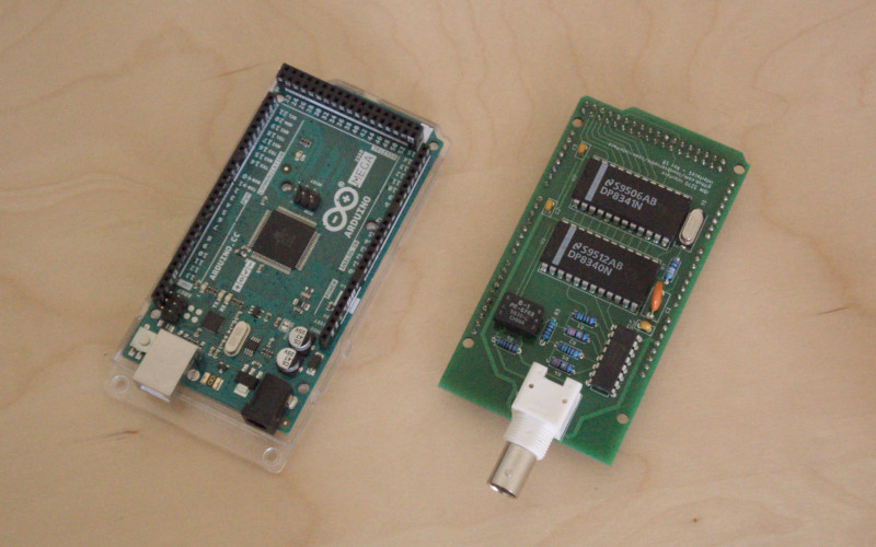
You can still find National Semiconductor DP8340 transmitters and DP8341 receivers on eBay, so I bought some along with the other components shown in the datasheet reference circuits. I had initially thought I'd have to build an interface from scratch, but these transmitter and receiver ICs provided the data link layer handling for me.
I also found an IBM 3174-23R rack-mount controller with Token Ring interface and thought I was ready to go. Unfortunately, the control program floppy disk was corrupt, and only the diagnosis disk could be loaded. The diagnosis program did display menus on the terminal, which was sufficient to capture some traffic between the terminal and the controller for analysis.
I built a simple receiver circuit from the DP8341 datasheet on a breadboard, attached it to an Arduino Mega, and using a tee connector tapped the wire between controller and terminal. I was very excited when the DATA AVAILABLE pin went high for the first time, and my interrupt handler was called. It took me a while to reliably read data from the receiver. I soon discovered I was overflowing the Arduino Mega's 8 KB of memory, and the data rate was too fast to to unload the data to my PC over the serial port in real-time.
The majority of the messages I captured were poll commands from the controller and acknowledgment responses from the terminal. Because the controller initiates all communication, it has to poll the terminal to check for keypresses continually. After filtering out the no keypress messages, I was able to map the scan codes returned by the terminal to the keys.
I also captured load address counter and write data commands associated with the display buffer. Extracting the addresses was easy, but I did not see the data written to the display buffer in the EBCDIC encoding that I expected based on the diagnosis interface shown on the terminal, it wasn't ASCII either. It turns out the terminal uses a different character encoding, I don't know what it's called and couldn't find any reference to it. I had enough examples from the diagnosis interface to build most of the mapping from captured data. When I added the DP8340 transmitter to the breadboard was able to generate a complete mapping after first writing "hello world," of course!
3270 terminals have a status line shown at the bottom of the display. Other than the current cursor position, the status line is managed by the controller. Confusingly the status line starts at address 0 of the display buffer, although it is at the bottom of the screen, address 80 is the top-left cell in 80 column mode. Also, the character encoding for the status line is different and includes many unusual symbols.
Eventually, I was able to create a Python library, pycoax, to serialize and deserialize 3270 frames - the Python code runs on your PC and communicates with the Arduino over serial (really USB).
Finally, I designed my first PCB using KiCad and sent the design off to JLCPCB. $15 and a week later, I had 5 Arduino shields ready to assemble. The PCB was a considerable improvement over the breadboard circuit, and I noticed a dramatic reduction in receiver errors. Ok, I admit there was a routing mistake the first time around - I did have to order a revision!

Creating oec
My goal was to build a replacement for the IBM 3174 controller that I could use with Hercules. Now that I understood CUT type terminals don't process the 3270 data stream directly, I realized implementing VT100 emulation first would be easier than TN3270.
I found pyte, which provides in-memory VT100 emulation that I could connect to a process (such as a shell or SSH). All I had to do was poll the terminal for keypresses, pass these to the process, update the pyte emulator with the process output and then write the emulated terminal screen to the terminal - some mapping required. And repeat. Other than that, I had to watch for a terminal being attached (powered on) or detached and monitor the process health.
Maintaining a copy of the screen in the controller memory as I do is not how early controllers operated in an era where memory was expensive. Instead, the CUT terminal provides commands to read from the display buffer and to find cells matching a particular pattern, such as an attribute indicating the start of an unprotected field. Without the same resource constraints, I found it far easier to maintain a copy of the screen and update the terminal with what changed.
Inspired by pyte, I wrote pytn3270, a pure Python TN3270 library providing similar in-memory emulation. Integrating this with the controller required little change; all I had to do differently was to map the field attributes to the 3270 terminal attribute byte. I could have used x3270, but I wanted a better understanding of the telnet protocol and 3270 data stream. I've only implemented the bare minimum of the TN3270 protocol, but it is enough to connect to z/OS, and a pure Python library may be useful beyond this project.
Today oec is far from providing all of the IBM 3174 controller features, but it is useable.
You can find oec on GitHub.
The future
First, I want to add a connection menu so you can select the host (it can only currently connect to a single host) and multiple logical terminal support. Later EAB and TN3270E support - I'll need to implement some missing pytn3270 features to support those.
I'm working on an FPGA based interface that doesn't depend on obsolete National Semiconductor ICs - learning a little more about the protocol and some Verilog in the process.
I'd love to hear from you if you are interested in any of this. There is very little out there currently about these terminals, I may have pieced what does exist and the history together incorrectly - any corrections, clarifications or additional information is welcome!